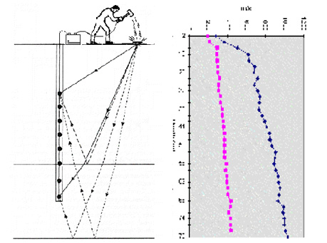
surface in increments down the borehole. Downhole seismic surveys are the simplest and cheapest method for borehole seismic techniques, as only one borehole is required for these surveys. Seismic energy is generated on surface at a fixed distance from the top of the borehole. P-wave energy is normally provided by a hammer and plate or weight drop similar to shallow seismic reflection and refraction profiling surveys. Polarised S-waves are generated using a shear wave hammer. This comprises two hammers connected to either end of a plank that is held to the ground using a vehicle or heavy weight.
Collecting both positive and negative polarised (so called A and B) S-waves using the two hammers separately, enables the S-wave arrivals on the receiver shot records to be distinguished from those of P-waves and coherent noise. The travel times of the first-arrival seismic waves are measured at regular intervals down the hole using a string of hydrophones/geophones in case hole is dry or, in the case of S-wave surveys, a single clamped triaxial geophone is gradually moved down the hole.
The P- and S-wave arrival times for each receiver location are recorded and used to make travel-time versus depth curves for the complete hole. These curves are used to determine total velocity profiles from which interval velocities are calculated. These velocities and density data from geophysical logging of the borehole are used to calculate various elastic modulus such as Young’s Modulus, Bulk Modulus, Poisson’s ratio etc.
Crosshole seismic surveys involve measurement of the travel time of seismic energy transmitted between two or more boreholes in order to derive information on the elastic properties of the intervening materials. One hole is used to deploy the source whilst the other hole(s) are used to detect the arrival of the seismic energy. The receiver is same as in downhole seismic, a tri-axial geophone, which usually clamps to the walls of the borehole. The travel times of the seismic waves are derived from the first-arrivals identified on the seismic trace for each shot-receiver position and are used with the known distance(s) between the shot/receiver boreholes to calculate the apparent velocities (P and S) for each depth interval. Accurate 2-D maps of seismic velocity variations between boreholes can be produced by processing the data using specialized software.
These velocities and density data from geophysical logging of the borehole are used to calculate various elastic moduli such as Young’s Modulus, Bulk Modulus, Poisson’s ratio etc like in Downhole seismic survey. Final results are generally displayed as tables or profiles of the calculated elastic moduli.
Applications: