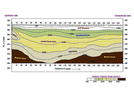
The seismic refraction method is based on the measurement of the travel time of seismic waves refracted at the subsurface layer’s interfaces due to dielectric contrast. Seismic energy is generated on surface by a source ('shot' using Hammer & Plate, weight drop or small explosive charge). Energy thus generated travels from the shot point either through the upper layer (direct arrivals), or down to and along underlying layer with higher velocity (refracted arrivals) before it returns back to the geophones implanted at surface at regular intervals. Beyond a certain distance from the shot point, known as the cross-over distance, the refracted signal is observed as a first-arrival signal at the geophones (arriving before the direct arrival). Observation of the traveltimes of the direct and refracted signals provides information on the depth profile of the refractor.
In order to receive the refracted energy as first arrival at each geophone shots are taken at and beyond both ends of the geophone spread. Data is thus recorded on a seismograph and first-arrival times to the geophones from each shot position are detected from the records. Travel-time vs. distance graphs are used to calculate the velocities of the overburden and refractor layers through analysis of the direct arrival and T-minus graph gradients.
Depth profiles for each refractor are produced by an analytical procedure based on consideration of shot and receiver geometry and the measured travel-times and calculated velocities. The final output comprises a depth profile of the refractor layers and a velocity of the subsurface layers.
One of the major applications of seismic refraction is to determine the bedrock type & depth. As seismic velocity is directly related to the elasticity and density of the material through which the seismic waves area traveling, seismic velocities provide a measure of material strengths and can also be used for assessing rippability and rock quality. The technique can be used for mapping depth to base of backfilled quarries, depth of landfills, thickness of overburden and the topography of groundwater.
Applications: